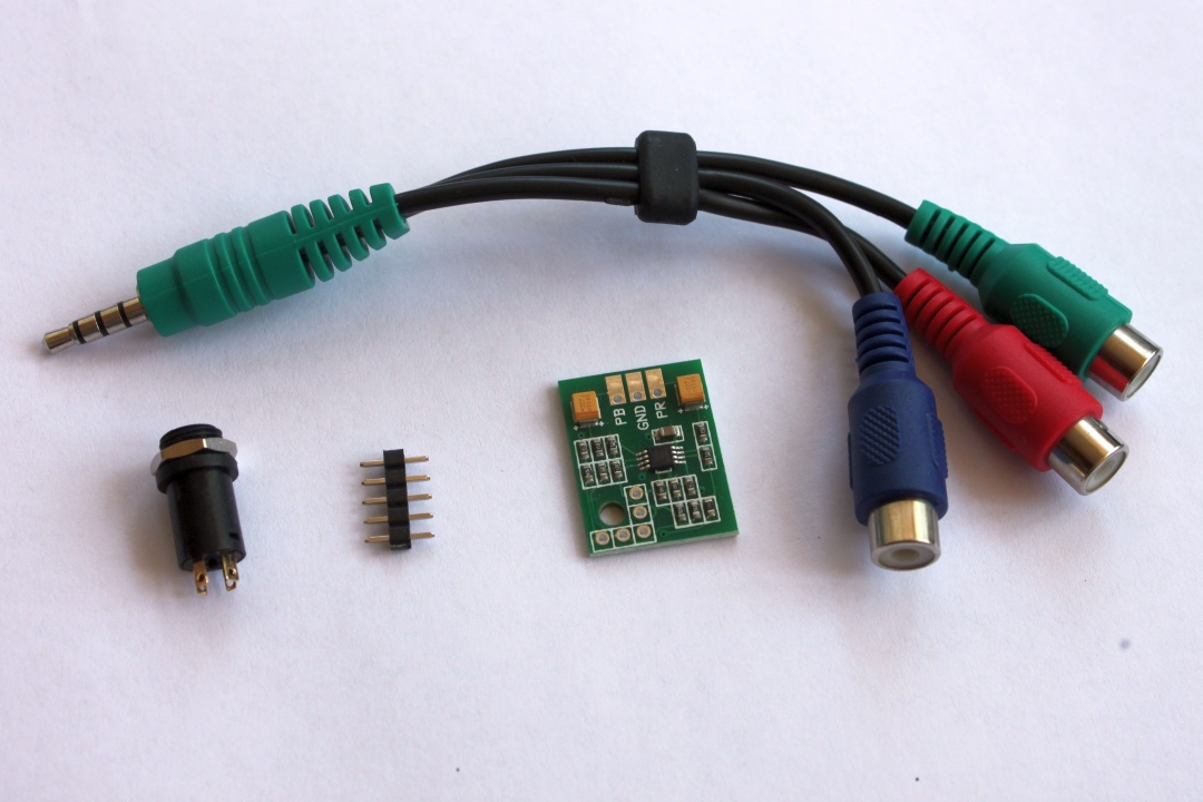
- 3.5mm/4P jack to 3 x phono (RCA) cable
- 3.5mm/4P jack panel socket
- 5 pin header
- NESRGB-COMPONENT board
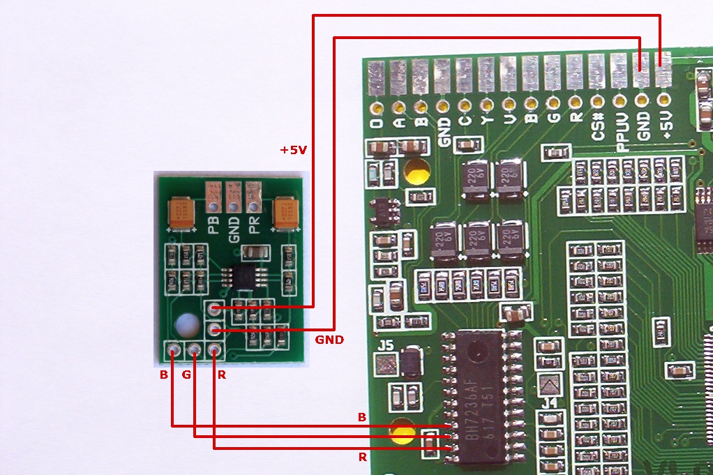
- GND
- Y (from the NESRGB board)
- PB
- PR
Click on the pictures to make them bigger.
|
Contents:
|
|
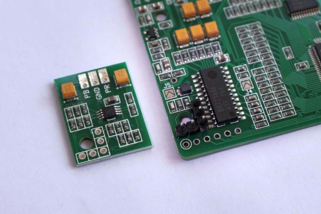
Break the pin header in two parts. One two pin, one three pin. Insert the into the NESRGB board at the location shown. |
|
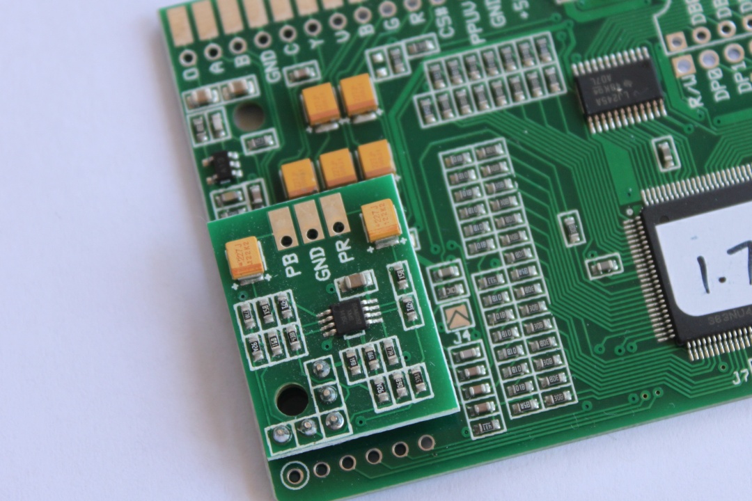
Solder the NESRGB board into place. |
| Now mount the 3.5mm/4P socket. Use a drill with a step drill bit to drill an 8mm diameter hole in the console's shell. The socket can be mounted in plastic up to 2.3mm thick. If the console wall is thicker than this, insert a large (>10mm) twist drill bit into the hole from the inside of the shell. Slowly twist the drill bit by hand to remove some of the plastic from the inside of the hole which will allow the connector to be recessed. | |
Wire up the 3.5mm/4P
socket. Look carefully at the rear of the socket to see the four
pins labelled by number. Wire the connector according to the
following list.
|
|
| |
These instructions are for the NESRGB12 board. Those with the original version board which is marked only 'NESRGB' (sold prior to May 2014) will have to solder the component board directly to the pins on the video encoder chip. |
Change Log
22/12/2014 - Page created.