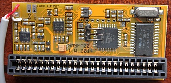
Sega Master System FM Sound Expansion Board
The Japanese Sega Master System included a Yamaha YM2413 FM synthesis chip along with the standard PSG sound. Many games, some of which were never even released in Japan, contain extra FM sound and music. Installing this board will add FM sound capability to any Master System or Mark III game console. The first post in this thread contains a list of games with FM sound. A switch is provided with the board to disable the FM chip and revert to the PSG sound whenever desired.
New in version 2.0One of the most popular games with extra FM sound is Monster World III: The Dragon's Trap. This game is programmed to use the FM sound hardware only if it detects that is is running on a Japanese SMS (or Mark III). Hardware version 2.0 and above has a region switch feature. Instead of a two position switch, a three position switch is now supplied which can be used to select between off position (PSG), FM, or Japanese/FM.
New in version 2.2
The method for region switching (disable the I/O chip with KILLG# upon
receiving a write to port 0x3F) is not totally reliable. Approximately
5-10% of consoles do not respond. Hardware version 2.2 fixes this
problem with the addition of one extra wire to the installation. In late
2014 there was some extra details discovered about the Japanese SMS
sound hardware on detailed in this
thread. The benefit is there are no longer 'extra' sound effects
playing in Outrun at the start of a race.
| After Burner | Golvellius - Valley of Doom | Scramble Spirits |
| Alex Kidd: The Lost Stars | Great Golf * | Shanghai |
| Alien Syndrome | Hoshi wo Sagashite... | Shinobi |
| Altered Beast | Kenseiden | Solomon no Kagi - Oujo Rihita no Namida |
| Aztec Adventure | Lord of the Sword | Space Harrier 3-D |
| Blade Eagle 3-D | Maze Hunter 3-D | SpellCaster |
| BMX Trial Alex Kidd | Megumi Rescue | Super Racing |
| Bomber Raid | Miracle Warriors | Tennis Ace |
| California Games | Mônica no Castelo do Dragão | Tensai Bakabon |
| Captain Silver | Nekkyuu Koushien | Thunder Blade |
| Casino Games | Out Run | Time Soldiers |
| Cloud Master | Out Run 3-D | Turma da Mônica em: O Resgate ++ |
| Cyborg Hunter | Parlour Games | Ultima IV: Quest of the Avatar |
| Double Dragon | Penguin Land | Vigilante |
| Fantasy Zone II | Phantasy Star ** | Wonder Boy III: The Dragon's Trap ++ |
| Fantasy Zone: The Maze | Poseidon Wars 3-D | Wonder Boy in Monster Land |
| Galactic Protector | Power Strike | Y's: The Vanished Omens ** |
| Galaxy Force | Rampage | Zaxxon 3-D * |
| Game Box Série Esportes Radicais | Rastan | Zillion II: The Tri Formation |
| Global Defense | Rescue Mission | |
| Golfamania | R-Type |
Key
* Only the North American and Japanese release supports FM sound.
** Only the Japanese version supports FM sound. It was removed from other language versions.
++ This game requires the region switch set to Japan to play FM sound.
For those that have Pro Action Replay / Flash cartridges: The following games support FM sound but require a with a minor patch to make it work. More information here.
| Battle Out Run |
| Double Hawk |
| Dynamite Dux |
| Rambo III |
| Summer Games |
For those with Flash cartridges: There are some interesting patches available.
| Ys US Master System FM sound patch | A patch for the Ys US version to put FM sound back in. |
| Phantasy Star retranslation | Phantasy Star Japaese to English translation, has FM sound intact. |
| Sonic 1 FM | Sonic with new FM music. |
Version 2.2 - Available now.
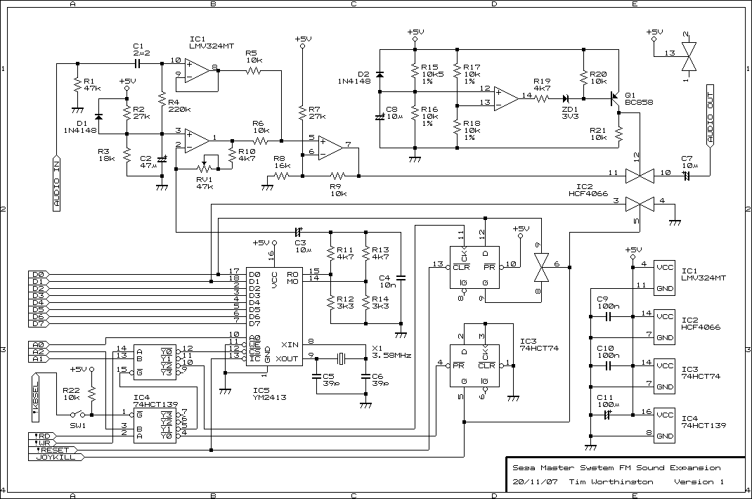
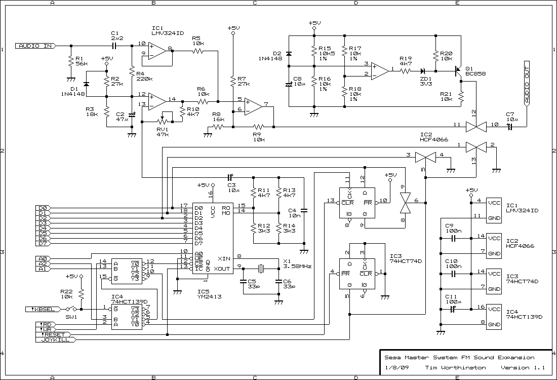
Circuit Diagram
Logic Equations (AHDL)
Installation
The SMSFM board is designed to plug into the expansion slot of an original model Sega Master System console. To fit the board, first remove the screws and open the console. Plug the SMSFM board into the expansion connector. It fits in the cavity behind the cartridge slot and does not require the plasic cover of the expansion port to be punched out. It is usually necessary to cut away part of the metal shielding for the SMSFM board to fit.
A switch is provided to disable the SMSFM board. This is useful for games which you prefer the PSG audio and a few games that crash when they detect FM sound hardware. The version 2.2 board comes with a three position switch. The third position switches the region of the console to Japan. The region switching feature doesn't work on all consoles. If it doesn't work please see instructions for adding the extra region switch wire towards the bottom of the page.
Attaching the card edge connector
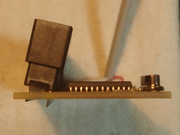
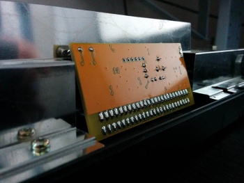
Solder the the card edge connector to the side of the board with the components mounted. Tilt it slightly towards the centre of the board. You will also need to bend or cut away the part of the metal shield over the expansion slot.
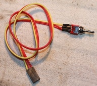
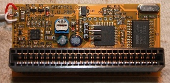
Wiring the switch
Solder the bare wires of the separate 3 wire cable to the switch. The other end of the cable has a connector attached. This mates with the 3 way header which should be soldered in position in the centre of the board like in the picture above.
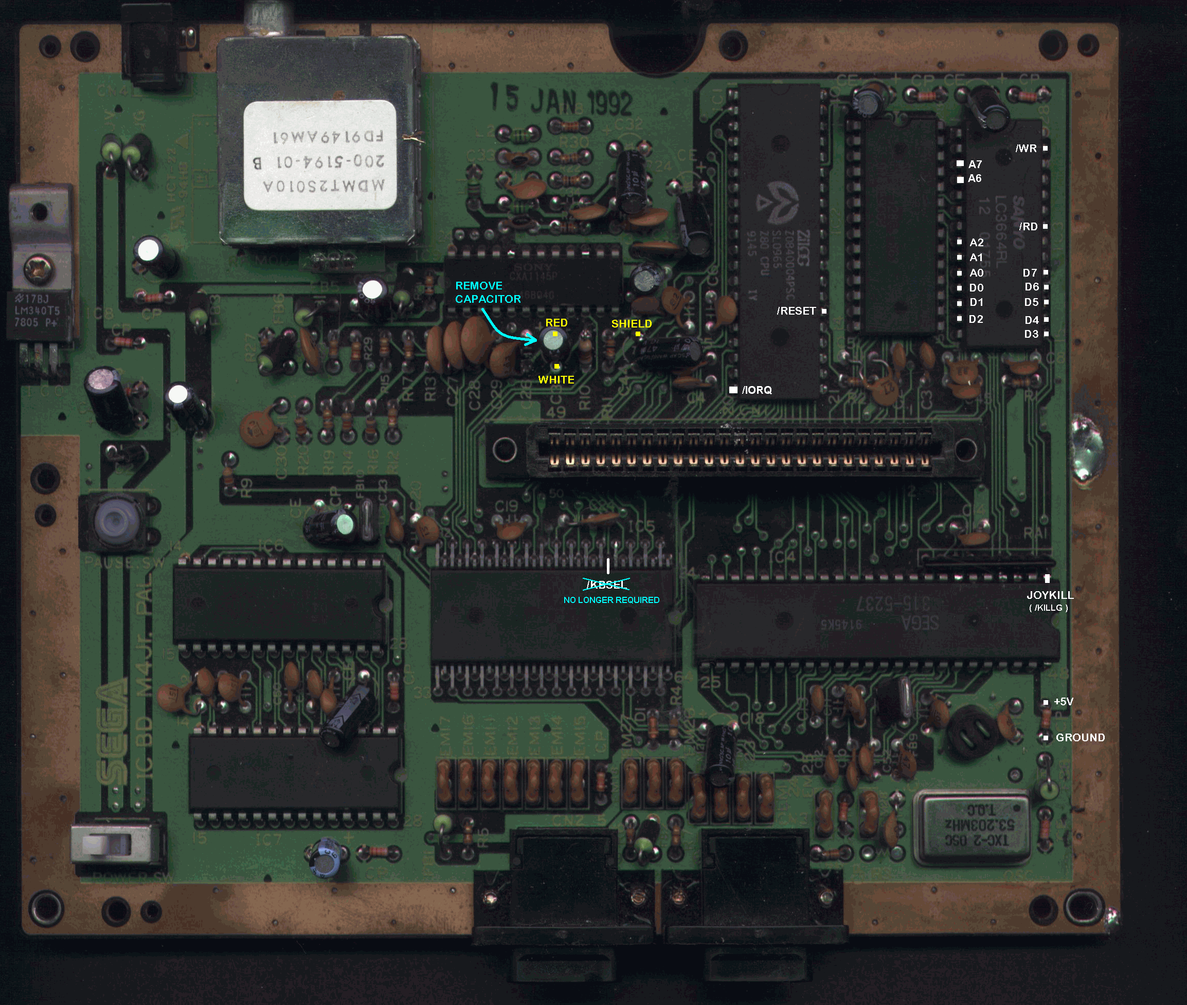
Audio mixing
Installation requires some soldering for audio mixing. A capacitor in
the audio circuit is removed and a two core shielded cable soldered into
its place. The standard (SN76489/PSG) audio signal is sent into the
SMSFM board via the white wire, is mixed with the FM sound signal, and
sent back through the red wire. The cable shield should be connected to
ground to reduce noise. Trimpot RV1 controls the volume of the FM sound
only. What follows is a collection of instructions for connecting the
audio mixing wires to various different version of SMS main board.
Please let me know if you can't find one that matches your hardware.
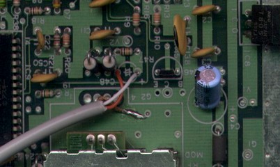
PAL SMS (original 1986)
Capacitor C48 (10µ aluminium electrolytic type) is removed, the white
wire is soldered to the +ve hole and the red wire to the -ve
hole. There's a large ground plane nearby to attach the shield. Access
to this cap first requires the removal of the voltage regulator
heatsink. This is done by first removing the screw on the 7805 voltage
regulator with a long shaft screwdriver, then unscrewing the two screws
holding the heatsink to the PCB. Don't forget to reattach the heatsink
before you finish!
PAL SMS 2
Capacitor C31, located beneath the video encoder IC, is removed.
White wire to -ve, red wire to +ve, and shield to nearby
ground point at the -ve leg of C44.
NTSC SMS
Remove C37, white wire to +ve, red wire to -ve. There's a
ground plane around the base of the capacitor so just scrape off a bit
of the green stuff and solder the shield to that. The heatsink on the
voltage regulator many need to be removed for access (remember to put it
back!). Because this PCB does not have plated through holes, soldering
cannot be done from the component side.
Note that the diagram below is incorrect, the white/red
indicators are swapped around.
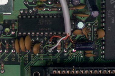
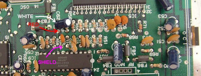
Late model PAL SMS (VA3)
Remove C62, white wire to -ve, red wire to +ve. The shield is
connected to a nearby ground plane - the leg of C59 looks like a good
choice.
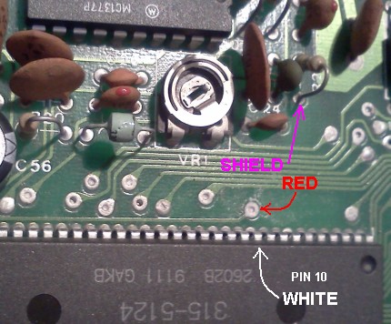
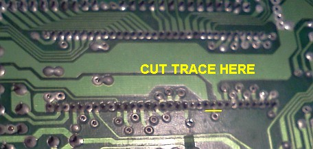
Brazilian Tectoy SMS (original version)
Locate CI-5, the 315-5124 VDP. Find the trace running from pin
10 and cut it close to the IC. Solder the white wire to pin 10 and the
red wire to the positive leg of C45 (that's where the trace goes). I
also have a circuit diagram for
reference.
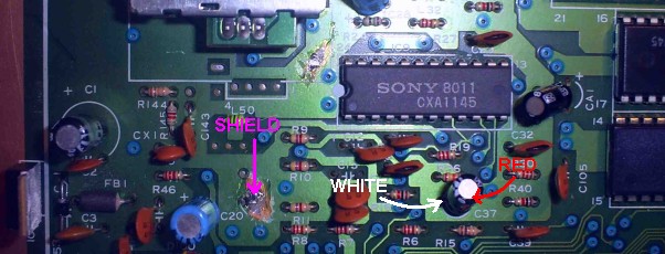
Original NTSC SMS (1986)
Remove capacitor C49, located left of the centre in the photo
below. Solder the white wire to the +ve leg hole and the red
wire to the -ve. Solder the shield to the nearby ground plane or
the RF modulator's metal casing.
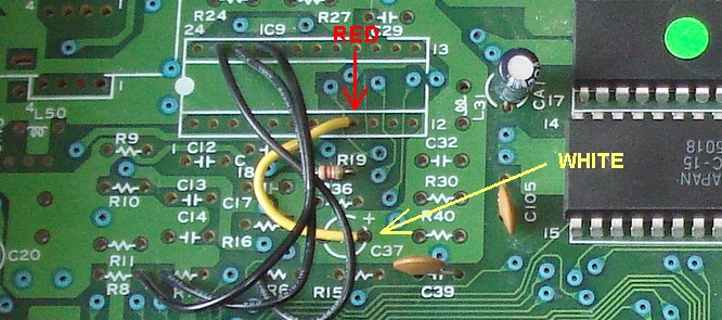
French M4 SMS (no video encoder, requires the Adapteur RVB)
Remove the yellow wire between the place for C37 and the place
for IC9. Solder the white wire to the +ve leg hole of C37 and
the red wire to IC9 pin 9. Solder the shield to the nearby ground plane
(scratch off the green) or to pin 1 in the place for IC9. Because this
PCB does not have plated through holes, soldering cannot be done from
the component side.
Generic SMS (those not listed above)
Trace the audio signal from both the RF modulator and A/V port (if there
is one) until they meet at a common point. Trace the audio signal back
further (it may go through an opamp or audio buffer inside the video
encoder IC) until you find an electrolytic capacitor in the signal path.
White wire = input to SMSFM board, red wire = output. Find a ground
connection close by and attach the shield. Keep in mind that the input
and output are electrically the same as those on a stereo system.
There's no reason why standard phono sockets can't be attached and the
mixing done with external leads.
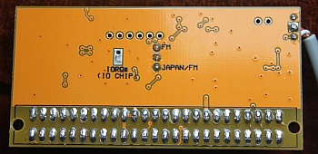
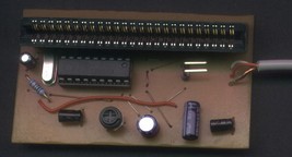
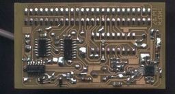
Solder Version
This is simply a board without a 50 pin edge connector fitted. In
order to install the board into a SMS2 or Mark III you will need to do
a bit of soldering.
In addition to the audio mixing, the solder in version requires 18
wires to be connected between the SMSFM and the Sega motherboard. The
type of wire using is not critical. Use what you are comfortable working
with, thin wire is usually easier.
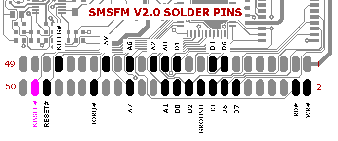
Solder diagram for PAL SMS 2
(updated)
KBSEL# is unused and should be left unconnected.
Extra wire for region switching.
Some consoles require an extra wire for region switching to work correctly.
The wire carries a modified IORQ# signal for the I/O chip. The IORQ# pin should be isolated from the rest of the circuit, either by cutting the track on the PCB or cutting and lifting the pin itself. Solder a wire between IORQ# pin and the IORQ# pad clearly marked on the back of the SMSFM.
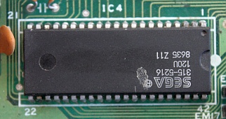
Sega 315-5216 - I/O chip inside an original Master System. IORQ# is pin 19.
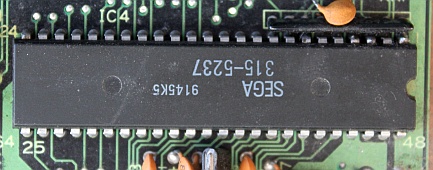
Sega 315-5237 - I/O chip inside a Master System 2. IORQ is pin 7.
Shop
See the etim online shop for price and availability.
Historical Hardware
|
Version 1.0 - 2007 There was a small problem with this board which made it
incompatible with a few of games. Read this
discussion on the SMS Power forums for more information
and a fix. Many boards also contained a defective YM2413 sound
chip, read more about it here. |
| Version 1.1 - 2009 Circuit Diagram 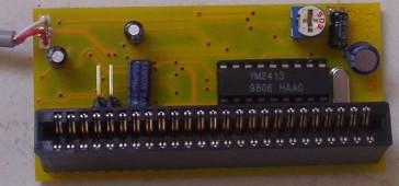  |
| Version 2.0 - 2012 Circuit Diagram Logic Equations (AHDL) 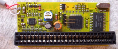 |
|
Version 2.1 - 2014 |
Changelog (D/M/Y)
8/3/2018 - Added extra details in the installation section about
soldering the edge connector and switch. Corrected the IOREQ# pin number
on the two I/O chips in the region switching section.
18/2/15 - Removed some info about old versions of the board. Rearranged
the page a bit. Added details for the V2.2 board, the game compatibility
list, and instructions for the extra wire for region switching.
2/4/14 - Added information about reliability of region switching, link
to shop.
15/2/14 - Revised time when new stock is expected.
17/11/13 - Run out of stock.
20/7/13 - Added diagram for French M4 board revision.
13/5/13 - Shop is open again.
26/4/13 - Shop is temporarily closed.
26/1/13 - Added information about V2.0 + shop + diagrams for the audio
mixing in the Brazilian Tectoy SMS.
12/8/10 - Added note to NTSC SMS instalation instructions, I'll make a
correct diagram one day when I have time.
29/8/09 - Updated with details on the new v1.1 board.
10/1/08 - Page created